 |
| FEATURES |
● UL ,CE & CQC safety approval.
● 2 Pole to 4 Pole are prepared with switching current of 7A (2 pole, 3 pole) and 5A (4 pole).
● PCB terminal and Socket terminal are selectable, and for direct panel mount, flange case type is available.
● Nominal power 900mW & AC 1.2VA.
● Operating power 510mW.
● Either with or without lamp is optional for AC & DC coil.
● Low coil power consumption with high response time. |
|
|
|
|
 |
UL FILE NO:E162117/E188367
TUV FILE NO:
CE DECLARATION OF CONFORMITY
CQC FILE NO: 04001009878
|
|
|
| ORDERING INFORMATION |
| 952 |
- |
4C |
- |
12 |
D |
P |
M |
L |
G |
- |
F |
|
|
|
| 1 |
|
2 |
|
3 |
4 |
5 |
6 |
7 |
8 |
|
9 |
|
|
|
|
1 |
Model Number
952 |
2 |
Contact Arrangement
2C = 2 Form C (DPDT)
3C = 3 Form C (3PDT)
4C = 4 Form C (4PDT)
|
3 |
Coil Voltage
DC:6-100V
AC:12-270V |
4 |
Coil Type
D:DC
A:AC |
5 |
Terminal Type
Nil = Socket Terminal
P = P.C.B. Terminal |
6 |
Cover Type
Nil = General Type
M = Flange Top Type
S = Special Type
E = Special Flange Top Type
|
7 |
Optional
Nil = General Type
L = With Lamp and Diode (DC Coil Type Only)
N = With Lamp B = With Push Button
T = With Lamp and Push Button
K = With Lamp and Diode and Push Button
(DC Coil Type Only)
|
8 |
Contact Type
Nil = General Type
G = Contact with Gold Plating |
9 |
Type of Insulation
Nil = Class A
F = Class F |
|
| |
| COIL RATINGS (at 20℃) |
COIL
TYPE |
Coil Nominal
Voltage (V) |
Coil
Resistance
(Ω+-10%) |
Pick-Up
Voltage (V)
<= |
Drop-Out
Voltage (V)
>= |
Nominal
Current
(mA) |
AC |
12 |
46 |
9 |
3.6 |
|
| 24 |
180 |
18 |
7.2 |
|
| 110 |
3750 |
82.5 |
33 |
|
| 120 |
4430 |
90 |
36 |
|
| 220 |
12950 |
165 |
66 |
|
| 240 |
18790 |
180 |
72 |
|
| 270 |
24150 |
202.5 |
81 |
|
DC Standard Coils |
6 |
40 |
4.5 |
0.6 |
150 |
| 12 |
160 |
9 |
1.2 |
75 |
| 24 |
650 |
18 |
2.4 |
37 |
| 48 |
2600 |
36 |
4.8 |
19 |
| 100 |
11000 |
75 |
10 |
9 |
|
|
| * Max Continuous Voltage at 20℃:? 130% of Coil Nominal Voltage. |
CONTACT RATINGS |
| ●Contact Arrangement |
|
|
2 Form C (DPDT) |
|
3 Form C (3PDT) |
|
4 Form C (4PDT) |
●Max. Switching Power |
|
|
|
2 Form C (DPDT) |
2 Form C 1750VA 210W |
|
3 Form C (3PDT) |
3 Form C 1750VA 210W |
|
4 Form C (4PDT) |
4 Form C 1250VA 150W |
●Max. Switching Voltage |
|
|
2 Form C (DPDT) |
250VAC 30VDC |
|
3 Form C (3PDT) |
250VAC 30VDC |
|
4 Form C (4PDT) |
250VAC 30VDC |
● Max. Switching Current |
|
|
|
2 Form C (DPDT) |
7 A |
|
3 Form C (3PDT) |
7 A |
|
4 Form C (4PDT) |
5 A |
●Contact Resistance |
|
|
2 Form C (DPDT) |
<= 100 mΩ |
|
3 Form C (3PDT) |
<= 100 mΩ |
|
4 Form C (4PDT) |
<= 100 mΩ |
●Resistive Load |
|
|
|
2 Form C (DPDT) |
|
|
3 Form C (3PDT) |
|
|
4 Form C (4PDT) |
|
●Contact Material |
|
|
2 Form C (DPDT) |
Ag Alloy |
|
3 Form C (3PDT) |
Ag Alloy |
|
4 Form C (4PDT) |
Ag Alloy |
●Inductive Load |
|
|
2 Form C (DPDT) |
|
|
3 Form C (3PDT) |
|
|
4 Form C (4PDT) |
|
●Pilot Duty Load |
|
|
2 Form C (DPDT) |
|
|
3 Form C (3PDT) |
|
|
4 Form C (4PDT) |
|
●Rating Load |
|
|
2 Form C (DPDT) |
2 Form C 7A/250VAC 7A/30VDC |
|
3 Form C (3PDT) |
3 Form C 7A/250VAC 7A/30VDC |
|
4 Form C (4PDT) |
4 Form C 5A/250VAC 5A/30VDC |
●Tv Rating |
|
|
2 Form C (DPDT) |
|
|
3 Form C (3PDT) |
|
|
4 Form C (4PDT) |
|
●Remark |
|
|
2 Form C (DPDT) |
|
|
3 Form C (3PDT) |
|
|
4 Form C (4PDT) |
|
|
|
CHARACTERISTICS |
| ●Electrical Life |
100,000 |
●Mechanical Life |
10,000,000 |
●Initial Insulation Resistance |
Min. 100MΩ 500VDC |
●Contact Resistance (Initial) |
≤100mΩ |
●Operate Time |
≤25ms |
●Release Time |
≤25ms |
●Initial Dielectric Strength |
50/60Hz 500VAC 1 min. (between open contacts)
50/60Hz 1500VAC 1 min. (between contacts and coil)
50/60Hz 1500VAC 1 min. (between contact sets)
|
● Vibration Resistance |
Malfunction: 10 to 55Hz at Double Amplitude of 1.5mm
Destructive: 10 to 55Hz at Double Amplitude of 1.5mm
|
●Shock Resistance |
Malfunction: 10G (11ms) / Destructive: 100G (6ms) |
●Ambient Temperature |
-25℃~+55℃ |
| ●Relative Humidity |
85% at 40℃ |
| ●Unit Weight |
Approx. 35g |
| ●Remark |
|
|
| Referential Data |
 |
| OUTLINE DIMENSIONS |
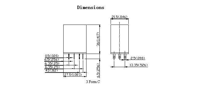 |
| OUTLINE DIMENSIONS |
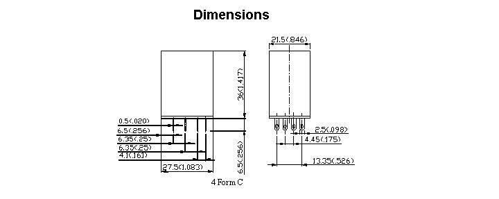 |
| OUTLINE DIMENSIONS |
 |
| Internal Connections |
 |
| Internal Connections |
 |
| Internal Connections |
 |
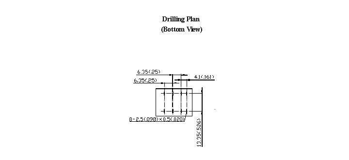
| Drilling Plan |
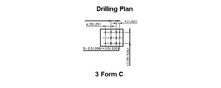 |
| Drilling Plan |
 |
| Drilling Plan |
 |
|
952 Series Relay.pdf Download  |
|
